
Having been out on the road a while now, I’m catching up on the remodel that got me here.
After I finished with the 110v AC (alternating current) system, I turned to the 12v DC (direct current) system. This is what you may be familiar with as what you find in your vehicle. The cigarette lighter outlet (more properly referred to as a “bayonet” port) is a 12v DC outlet. You probably use yours most with a phone charger or GPS navigation system.
Recreational vehicles contain both systems. The beauty of the 12v portion of the system is that it can and does operate free of outside electrical hookups. The pain of it is that you must find a way to keep your house battery(ies) otherwise charged up.
Though this system charges via the 7-pin plug that also operates the RV’s external safety lighting (for a trailer) or via an internal hookup (for a motorhome) while you’re driving, that charge only lasts a few hours, especially if you use lots of interior lighting, charge your devices, or operate 12v accessories such as fans or radios.
The two most popular methods to charge house batteries are the use of a generator (internal in larger RVs or external in smaller ones) or a solar panel system. As of this writing, I am getting ready to have a solar charging system installed, but will also carry a gas-powered external generator just in case. Properly hooked up, both of these methods can charge both 12v and 110v systems.
Foredeck 12v Charging Stations
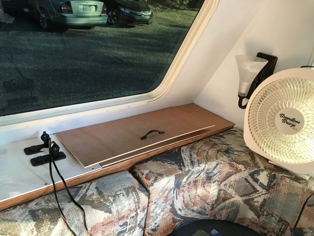
Since I had begun with the 110v outlets I put in up front, we’ll continue with the 12v charging outlets I installed on the starboard side of the foredeck’s center console.
The first thing I had to do was figure out where to attach the wires to tap into the trailer’s existing 12v wiring system. That would obviously be through the fusebox, and I knew from my work with the 110v system where that was. It’s located amidships, near the floor and beneath the cutout for the microwave oven in my galley kitchen cabinets. I just had to release and drop the top half of the access panel cover to reveal the ports.
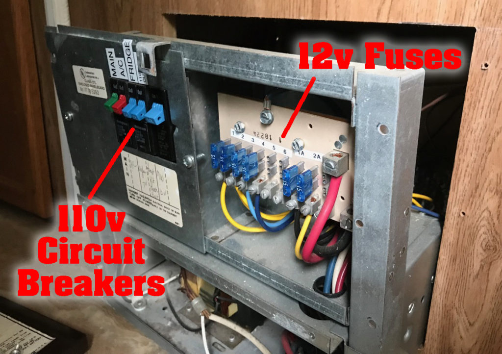
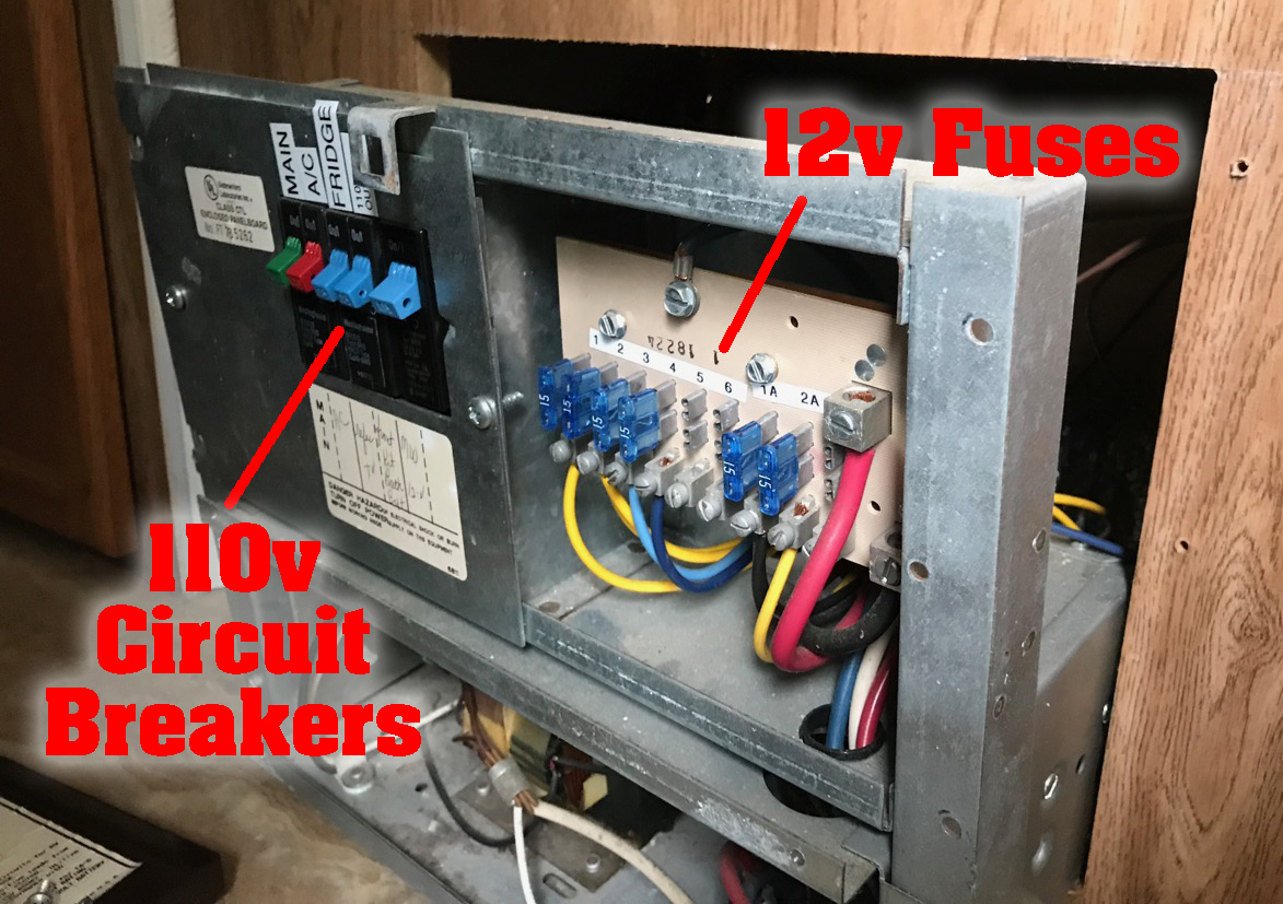
This shows the location of the 110v and 12v electrical hookups.
The trick was taking time to familiarize myself with the difference between the 110v circuit breaker panel (just like you have in your house) and the 12v fuse panel (just like you have in your car). the fact that I have experience working with both really helped me discern what I needed to work with and what I needed to leave alone.
For both types of hookups, one must access the back of the fusebox—to lead each wire to the proper circuit breaker or fuse for each circuit—and what’s called a “bus” — a metal bar screwed, in this case, into the floor of my trailer beneath the kitchen cabinets. This serves to ground all circuits to the steel frame of the trailer, which ensures—as it does in a house—that I won’t be electrocuted when I use any of my electric appliances.
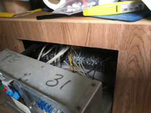
The fusebox’s previous hookups used fairly short wires, limiting my access for new work.
As you can see in the picture here, the length of the existing wires only allowed it to be pulled so far away from the cabinet. This made getting my hands and lower arms inside to manipulate the wires and screws rather difficult, as it severely impaired access.
I love my labelmaker, and have kept it working to keep me safe throughout my work on the trailer’s electrical system.
I knew it would be very easy to get confused about which wire was what, which can be extremely dangerous when working with electricity. So even though I was working with the batter disconnected and no outside electrical hookups, you can bet I worked very slowly, methodically, and triple-checked every connection before I made them. I also was pretty anal about labeling the lines with my labelmaker. Yes, I love that thing. It has probably saved me, more than once, from accidentally killing myself.
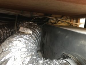
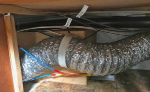
That silvery tube is the onboard furnace ductwork. The furnace runs on the 12v battery system, meaning it will work whether I have external electrical hookups or not.
To give you an idea of the tight quarters I was working in, this photo shows how the wiring for both 110v and 12v had to run beneath the kitchen sink inside the cabinets and out beneath the port side dinette bench.
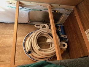
The port side dinette bench carries all of the foredeck wiring underneath. This area also opens to the outside via the hatch seen here, because it’s a storage compartment. This meant I had to keep all wiring running along the top so it wouldn’t get accidentally torn out when stuff moves during travel.
This all served as a chase to keep the wires together and relatively protected from damage, while also keeping them out of sight for good looks. Very useful, but not easy to work inside!
In the 110v installation blog, you saw how I pre-drilled the individual holes for the 12v USB and bayonet chargers. They came one of each to a two-hole cover plate, which I used as a template to place the holes.
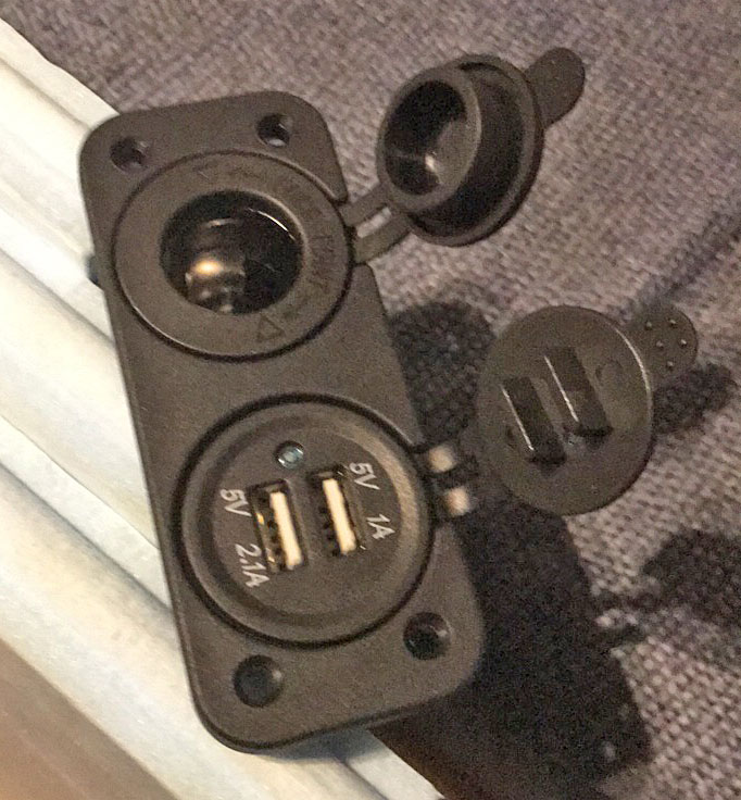
The 12v charging stations I chose had two outlets each: a bayonet charger and a 2-in-1 USB charger (5v 1 and 2.1 Amp, respectively). I wanted the option to use both types of outlets if needed, and that decision has turned out to be prescient.
I was happy to take the time and effort to splice fuses in where they were lacking, because fire scares the hell out of me.
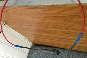
The individual positive wire running from each of these circuits included an inline fuse. That is, they SHOULD include such. Some of those delivered in my orders already had them. In others, I had to splice the fuse holders in myself, as you see here. This ensures that if one outlet goes bad, it doesn’t drag the whole system down, and it’s also a good protection against fire. And I like that.
The photo below shows how the double 12v outlet is wired, which you can’t see once it’s installed, because the wires are underneath the foredeck top shelf panel.
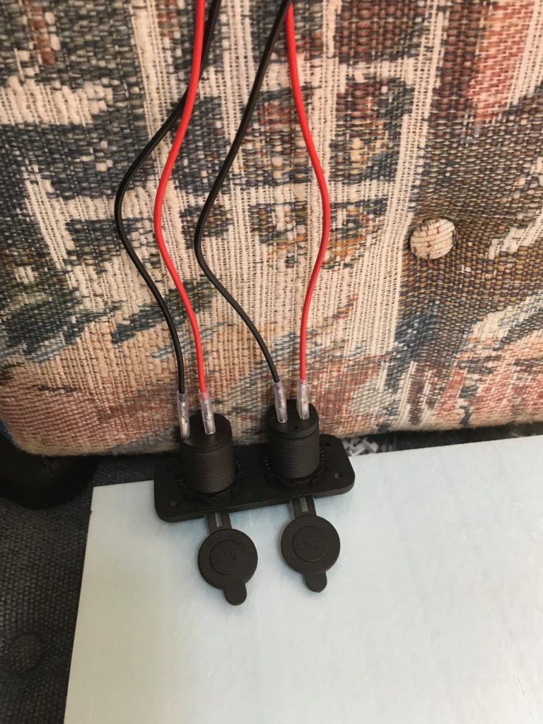
There are a total of four circuits (or, if you’re picky, two pos/neg circuit pairs) wired to each 12v outlet grouping I installed. This was a nice configuration, because I could swap out positions of each if desired, which it was in one case.
Below, you can see the pre-drilled holes of the second grouping awaiting placement of the components of a second set, while the top set is fully installed.
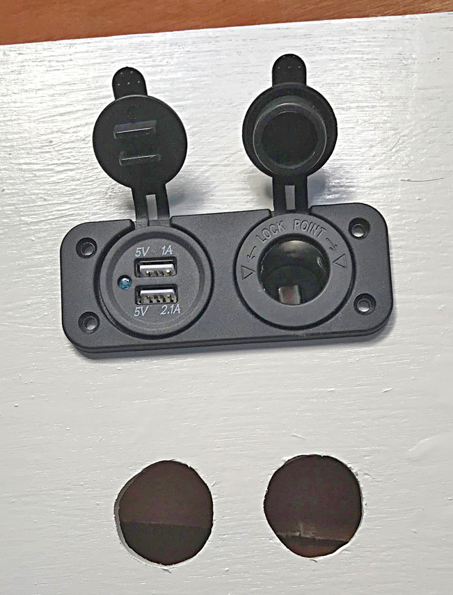
The cover plate or escutcheon I used for a template to locate the drilled holes for each outlet also acts as a backstop, which will be placed first. Then each outlet is dropped into the top, and a thin nut screwed up the back to snug it in place. I later was glad I had screwed, not nailed, the console cover in place, because after the first few weeks of travel, some of these nuts had worked themselves loose, and I had to go back in to tighten them.
After I had the second set of 12v outlets installed, I was so insanely glad to be able to plug in a 12v fan to move some air around in the hotbox my trailer had become already in the early summer swelter! It was a well-deserved treat for a job well done!
Aaaaahhhhhhhh!
Recent Comments