
Another in the series of renovations and upgrades that made it possible for me to go full time in my travel trailer.
As I originally intended to sleep in the bottom bunk and use the top one for guests, I realized there was a need for each to have its own smartphone charging station, so I got two more of the double units, one USB and one bayonet model in a single set.
The faceplate doubles as a locator template, making hole drilling fast, easy and accurate.
As in the foredeck installations, I used the faceplate/escutcheon as a template to position the holes for the three outlets.
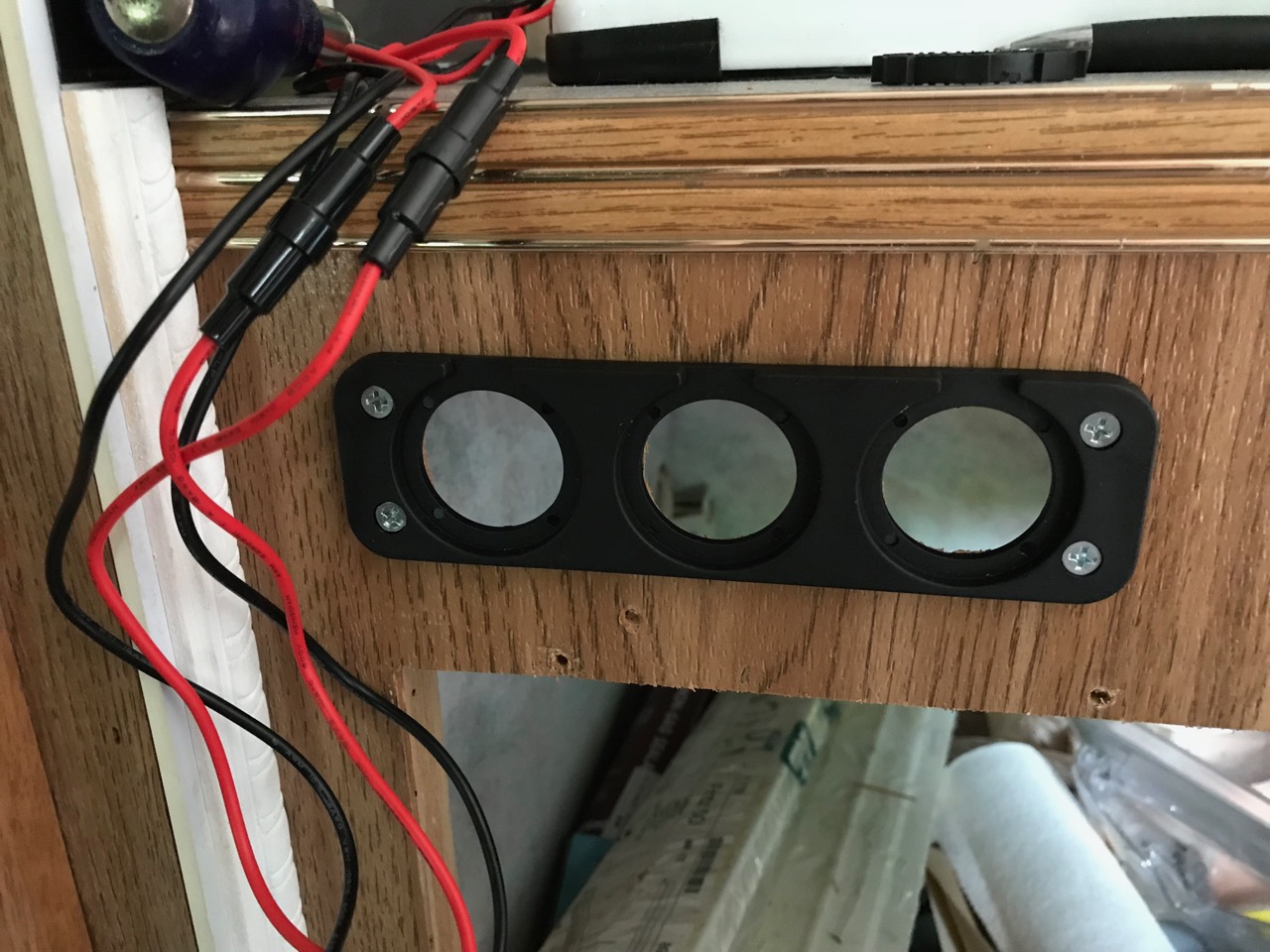
Here you can see the faceplate screwed in position after I cut out the holes with a 1-inch drill bit and my cordless drill driver.

In this case, the unit I installed amidships was a double charger and battery monitor readout, so this particular unit has three holes.
The three separate outlets — a double (2.1 and 5 a) USB charger, a bayonet-style charger, and a battery monitor readout) — are wired, to make sure I have left enough wire to tie the more distant chargers into.
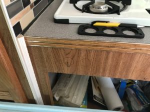
I have two bunks in the rear of the trailer, and wanted to be able to have a charging station in each, so the sleeping person could keep their phone nearby while charging.
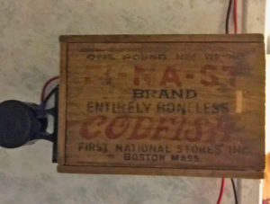
The old codfish box I used to house one of the bunk charging stations.
I used to collect old boxes and really wanted to keep some with me, so I used two old small codfish boxes as charger housings. Inside would hide the wiring behind the sliding top (mounted sideways on the wall), and phones can be laid on top of the box while owners sleep.
Later, I will hide the unsightly wires with thin wire covers.
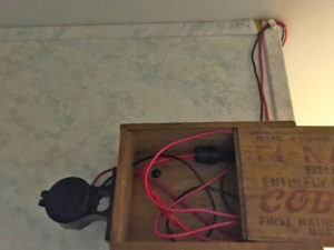
This view shows the sliding top closed and hiding interior wire mess, while charging port is still accessible to the left, with its cover in place.
I drilled two small holes in the side (now the top) of the box, to run the power wires up the wall.
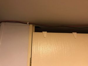
I ran the wires along the ceiling in front of the bathroom door, later to be cleaned up/hidden in a conduit channel.
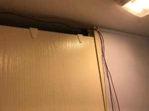
From there, I ran them around the corner and along the top of the bathroom door. Later, I would cover them will plastic wire cover sold at a nearby home center to make them attractive visually, and neat-looking.
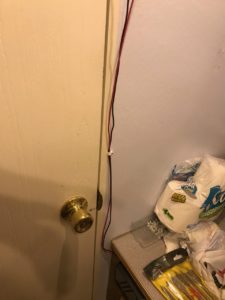
After crossing the door opening, the wires were routed on the wall along the right side of the door.
Here, the wires come down the other side. Again, these will later be hidden with attractive cover tubes.
At the end of the down-wall run, the wires enter the bathroom vanity cabinet.
From there, they run down the wall to the top of the bathroom vanity.
A better, direct view of where the wires run under the sink in the bath vanity
I drilled one larger hole to accommodate both wires. This, too, would later get covered for a finished look.
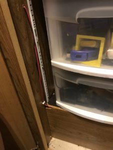
I ran the wires under the front of the sink/vanity, then drilled a hole into the pantry side and ran them down to the bottom and just behind the kickboard of the bottom pedestal.
From there, the wires ran along the inside top of the vanity and I brought them through a hole into the pantry, down the left inside wall, and into a dead space beneath the pantry shelving unit.
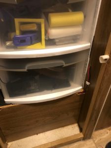
You can see where the wires will enter and emerge from the kickplate.
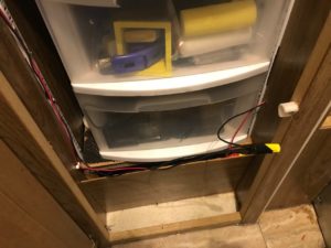
After I replaced the kickboard at the bottom, all the wiring would be hidden except where they went in and where they emerge.
The end result was a nice, clean, tucked-in look, and then I drilled a hole to run them under the kitchen cabinet.
You can see here where they emerge. Since the pantry is almost always closed, I didn’t bother covering there, but did make sure they’re tacked solidly so they don’t interfere with the drawers opening and closing.
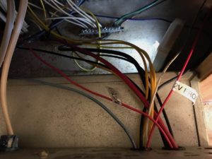
There, I connected the ground wire to the floor-mounted terminal bus, and the positive one to the fusebox terminal.
I used a labelmaker to create little tags for all the new wires I ran during the remodel, including these, so I’d know later what was what. I ran the new black ones (ground) to the terminal bar on the floor, then the red ones to the breaker panel.
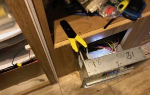
This gives you a good idea of how the breaker panel looks, with circuit breakers for the 110v system and fuses for the 12v.
This view shows the breaker panel fully wired and ready to be replaced. I underestimated the amount of wire I needed, so it was close, having enough to reach the unfastened breaker panel and still giving me room to work — a real squeaker, but I did it! I must add that I did all this work at a time when it was about 95° and 90% humidity, which made it a disgusting, sweaty, dirty job. Ugh.
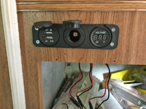
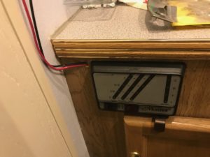
Here’s the finished 12v cluster, with the two USB ports at left, the 12v bayonet port in center, and the battery voltage monitor at right. They’re connected to each circuit in back and then held in place with a retainer nut. The black faceplate looks pretty sharp. I would have to mask it off later for painting.
Here’s the cluster, wired and screwed in place with retainer nuts. The two 12V outlets both have covers, so they look nice and neat when not in use. The area below is where the microwave goes, so I just ran those wires along the left-hand side inside, where they won’t be seen.
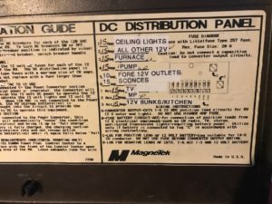
I used my labelmaker again to keep everything sorted on the panel’s front diagram.
I made sure to update the breaker panel labeling.
Ta-daaaaa! All powered up and working! I was pretty proud because this was my first-ever 12v wiring job. It’s pretty much like 110v, but a first-time anything is always a little nervous-making.
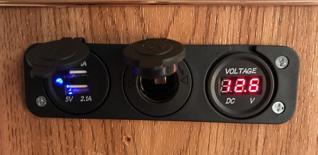
And here it is, all powered up and working as it should! Have to admit, I felt a good bit of pride at the completion of this part of the project.
I’ve gone on several mission trips and they give you a check list to ask what you will or will not do. My check list always only has one job that I wont do… wiring or anything with electricity. To me, a retired ICU nurse, electricity can start or stop your heart! You’re my hero Mary!
Ha ha, Sue! Almost everything I know about electricity, I learned in seventh-grade science class, except for a few things I picked up along the way. I’ll tell you this: Electricity follows a certain set of behavioral rules, so I find working with it a lot less angsty than working with people, who can be so unpredictable!
Ah yes, people can also start or stop your heart 🙂
You freaking amaze me. That is all.
Thank you, and that goes both ways.
Please pat yourself on the back for me, friend!
Thanks!